If you are interested in Electronics, you will likely ask yourself sooner or later if you need an oscilloscope and especially what to buy if you have decided to do so. As I have been in the same situation a few months ago I likely know what’s going on in your head. Give me a minute to save you a few more sleepless nights thinking about this topic.
You can find a lot of infos about scopes. You will find hundreds of hours of video reviews of scopes, just look at the amazing EEVBlog. But non if these videos really gave me an answer to my question: Do I actually need a scope and what can I do with it.
Did you love playing with your dads HIFI-system and turning the knobs? Well, I know a scope is kind of a sexy tool with it’s knobs for you… But do you really need one?
Yes, you need one, if …
… you really care about electronics. Seeing and therefore knowing what’s going on in a circuit is crucial to understand and perhaps fix it. And especially for my kind of learning it’s the most important tool to understand electronics and getting better in it.
What do I need and how much does it cost
Don’t buy crap. You just decided that you care about electronics, right? You want to understand and learn (from) it. So don’t buy a tool that is frustrating to use. And don’t buy a measurement tool that does show anything but not the signal you want to see. If you can’t trust the measurement you don’t need to measure!
I think the decision is a now brainer if you are a hobbyist: Rigol DS 1054 Z. It’s an awesome scope, and it’s an amazing scope given it’s price: Around 350-400 Euro. That is a log of money for a tool. But it’s so much fun digging around in a circuit, seeing what’s going on, rotation the knobs. I never really got it why Dave from EEVBlog and a few others are so addicted to scopes. Having one yourself and you understand it.
Save your money if …
… you are just playing around with electronics and your Arduino or Raspberry Pi starter kits. You will likely not invent something yourself (if you do so you care about electronics, right?) so your problems will likely be misconfigured wiring and the like. Looking closely at your circuit or doing it again from scratch will probably solve your problem. Get a good multimeter, that will be more than enough.
Interested in a longer version?
This blog post is mainly focused on what you can do with a scope and why that might be important to you. I don’t want to get too much into detail how you do that on a scope, I leave that to Dave from EEVBlog. He does a great job of showing every aspect of the scopes.

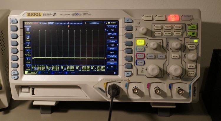
I personally owned a Rigol DS 1074 Z (bought before the 1054Z came out, arghh ;-)) which is basically the same as the 1054Z, but with 75 MHz bandwidth. I have been using it a lot the last days and thought it makes sense to share my experiences with it and how it helps me to understand and fix my circuits.
A scope is basically just a multimeter that measures the voltage in very short time intervals and saves the value measured. It then plots the values on screen like Excel does with diagrams. The various controls on the scope will allow you to navigate the “data cloud”.
If you are looking for a very specific situation you can setup triggers. A trigger is kind of a watchdog that will run a few tests on each datapoint acquired from the measurement unit. If the test fails, the point is dropped, if the test succeeds it begins to record the data points and displays them on the screen. This makes it easy to find out if your circuit is working as expected. Just setup the trigger, connect the scope to the circuit and run it. If nothing appears on the screen you know something does not work.
Building your own PCBs
I have been working quite hard the last months on a project. As soon as it is working I will provide more details on it. What I can say is, that it’s based on a custom Teensy 3.1 board. As I have written before I really like the Teensy approach and wanted to integrate it into my own product. I ordered the PCBs at oshpark.com and my components at mouser.com. After a few hours of soldering one PCB (I have parts and PCBs for building three devices) I did various tests with my multimeter to make sure I did not have shorts or other kinds of soldering issues in it.
Having finished first checks I plugged in the USB cable. If my PCB is working correctly it’s supposed to show up in the Serial-Port list of the Arduino IDE so I can program it. But nothing happened. In order to save power I did not add LEDs to the circuit. And I did not want to solder the LCD screen as they are quite expensive and I did not want to loose one on a prototype PCB before making sure all other components are working correctly. Staring at this PCB just doing nothing is so frustrating.
Without a scope I just would not have any chance to find the problem. I can test a few things with my multimeter, i.e. are the power pins showing up the expected voltages. Well, they did. But I cannot see if data is transmitted, if there is activity on I2C or SPI busses. And I cannot really measure if there is too much noise in my power supply, which might be a problem.

Teensy 3.x is using an IC that is running code which programs the empty Freescale ARM CPU with code which allows the Freescale CPU to be programmed with the Arduino IDE. According to Paul there are a few tests that you can do to see if the Bootloader IC is running. The reset pin on the MK20 will be low most of the time, but will go high every 50 milli seconds to just go low a few milli seconds later. With a multimeter you cannot see anything. It will just show zero or a few millivolts. Pressing the program button (I implemented one in my design) will pull the reset line low as long as you press the button. On my scope I could clearly see this is the case. So the Bootloader IC is working fine.
The Bootloader IC is expected to send some data to the Freescale MK20 as soon as you press the button because it will program it with code to allow the circuit to be detected as an USB-Device. This is my next test. Sending data often means a clock signal and a data signal (in this case it’s some kind of I2C type data transfer). You cannot see that on your multimeter, because even if it would be fast enough your brain would not be able to see the different voltage ratings – you see 24 frames per second on your TV and your brain is thinking that is moving stuff ;-). So your brain is quite limited in seeing differences more than a few times per second.

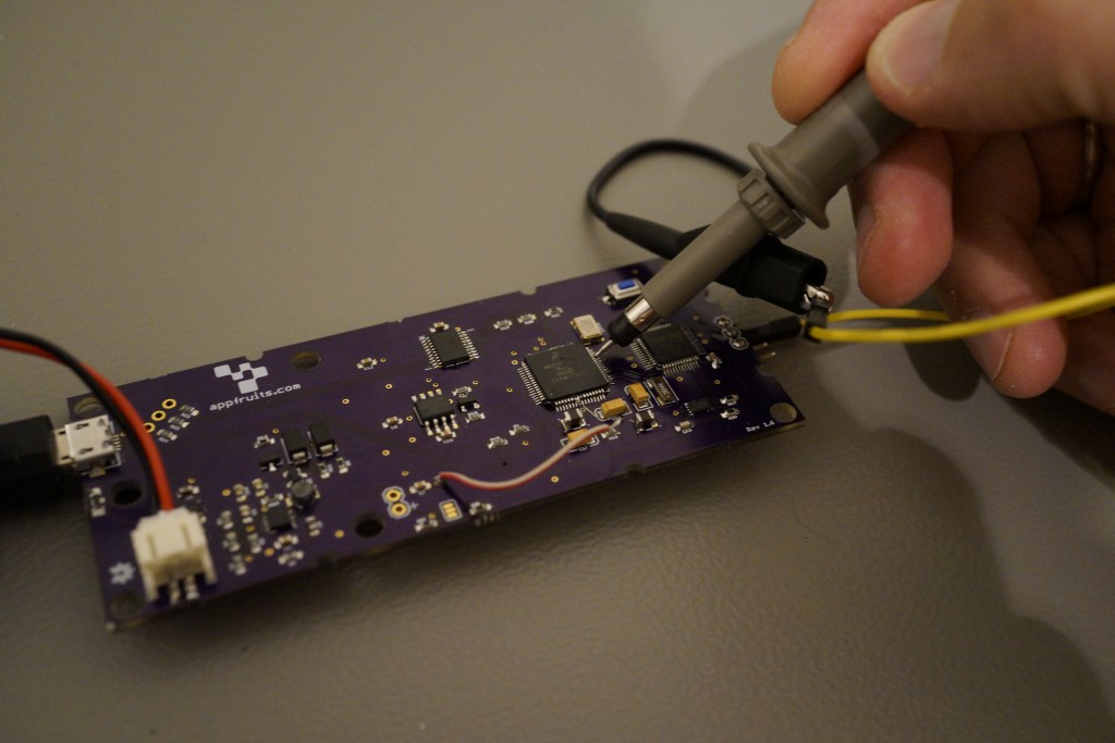
Placing the needle of the scobes probe (be carefully it’s really sharp!) on the IC pin, pressing the button clearly shows there is data transfer.
When the Freescale SK20 is programed it’s supposed to bring up it’s crystal. The crystal will clock with 16 MHz. You don’t have any chance to see that with a multimeter again. And the crystals I know don’t have a LED indicating everything is working fine ;-). Well, placing the scope, pressing the button and … nothing happens. The crystal does not work.
Paul (creator of Teensy) notes that it’s very important to have a good crystal design. Searching the data sheet of the crystal I bought to double check the specifications Paul gave in a forum post I noticed my mistake: I bought an oscillator and not a crystal. An oscillator has VDD and GND input and has one output pin with a clock. But Teensy expects just the crystal. Hammering my head on the table I realized two things:
- Using my scope showed my the problem in about an hour. Without it I would have a hard time in finding the bug.
- Always triple check every aspect of your design and components
I have ordered a batch of crystals and will keep you updated if that really solved my issues.
I hope I could help you answering the question if you need a scope or not. If I convinced you to buy a scope invest an hour a watch Daves extensive review on the DS 1054Z. Just to warn you: At the time of this writing the DS 1054Z is hard to get. You will likely have to wait a bit until you get one…


Thank you much!